
We are a professional manufacturer of organic fertilizer equipment and a customized service provider for fertilizer production lines
-
NO.313, Wanshan Road, Xingyang City, Zhengzhou City, Henan Province, China
Company Address
-
Call Us: +86-18703630069
(Sat - Thursday)
-
inquiry@hqhifertilizermachine.com
Our Email
Hydraulic Compost Turning Machine
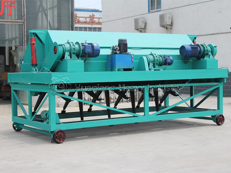
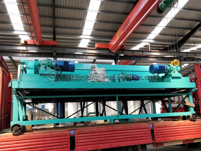
Equipment Introduction
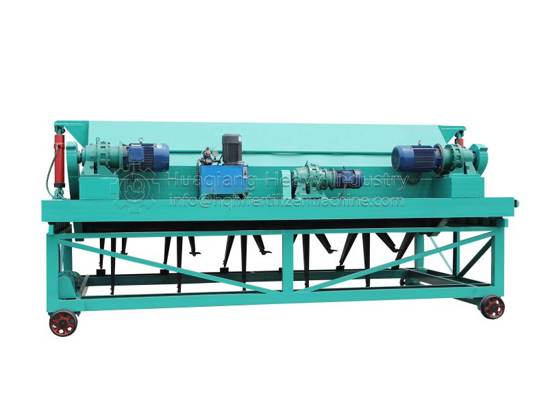
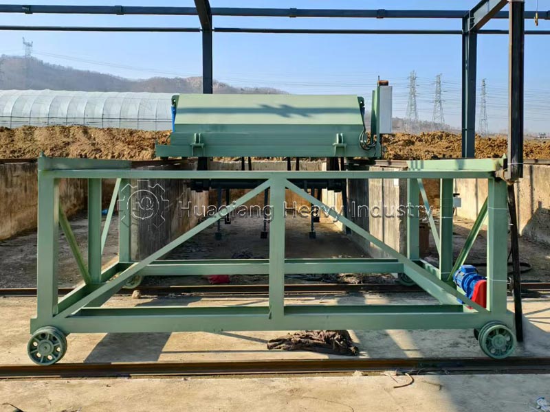
The hydraulic trough-type compost turner is a core fermentation equipment in organic fertilizer and bio-organic fertilizer production lines. Utilizing deep-trough fermentation technology, it provides the necessary oxygen for microbial fermentation and regulates material moisture through efficient stirring and turning, making it the preferred choice for large-scale fermentation plants.
The hydraulic trough-type compost turner is a turning device that operates in large-span, deep-trough fermentation tanks. Compared to ordinary compost turners, its biggest feature is the adoption of a hydraulic lifting system. It is a high-end core piece of equipment for trough-type aerobic fermentation technology, relying on a hydraulic lifting system to replace the traditional mechanical winch lifting structure, combined with a track-based chassis, and is specifically designed for deep turning, oxygen supply, crushing, mixing, and repositioning composting operations of various organic solid wastes.
Core Technological Advantages:
- Infinitely Adjustable Turning Height, Adaptable to the Entire Fermentation Cycle: Hydraulic cylinders drive the roller lifting mechanism, allowing for stepless adjustment of the turning depth from 0.5 to 2.0 meters. Shallow turning facilitates aeration in the early stages of fermentation, deep turning dissipates heat in the middle stages, and precise height control for dehydration in the later stages. This shortens the fermentation cycle by 3-7 days and increases the humus content of the finished product by 15%-20%.
- Flexible Hydraulic Transmission, Protected Under Heavy Loads: The hydraulic system adjusts the output torque in real time based on material resistance. It automatically buffers and releases pressure when encountering clumps or hard debris, preventing motor overload and burnout, and drive shaft breakage. It is suitable for high-humidity, high-viscosity livestock and poultry manure conditions.
- Adaptable to Large-Volume Fermentation, Lower Infrastructure Costs: The maximum turning depth reaches 2.5 meters, increasing the utilization rate of the fermentation tank by over 40%. For the same production capacity, the fermentation workshop occupies a smaller area, reducing civil engineering investment.
- High degree of automation and low labor costs: The control cabinet integrates manual/automatic modes, allowing preset walking speed, reciprocating turning frequency, and roller lifting height. Limit switches enable automatic stopping at both ends of the track, allowing a single person to complete the entire fermentation process.
- Smooth operation, low noise and low vibration: Hydraulic lifting eliminates chain winch impact, resulting in minimal machine vibration and significantly reduced wear on the frame and bearings. The overall equipment failure rate is lower than that of mechanical lifting models.
- Flexible multi-tank production: Equipped with a transfer vehicle, a single FPY hydraulic turning machine can switch between multiple fermentation tanks, significantly reducing the number of equipment required and adapting to the multi-tank parallel fermentation mode of large-scale organic fertilizer plants.
3) Applicable scenarios: It can be fully integrated with solar fermentation greenhouses, forced aeration systems at the bottom of the tank, automatic material feeders, and continuous discharge machines at the tank ends. The fermentation tanks support both continuous and batch discharge production modes, adapting to continuous organic fertilizer production lines.
Equipment Structure and Composition
The hydraulic trough-type compost turner adopts a modular design, mainly composed of the following six core systems:
- Frame and Main Structure
The main load-bearing frame of the equipment is made of high-quality carbon steel, treated with rust removal and anti-corrosion to resist corrosion from fermentation materials and extend the service life of the equipment. The heavy-duty frame design has strong load-bearing capacity and can adapt to long-term high-intensity deep turning operations.
- Power Transmission Device (Turning Power System)
Composed of a motor, reducer, sprocket, bearing housing, main shaft, etc., it is the core device that provides power to the turning drum. The motor transmits power to the cycloidal pinwheel reducer, which then transmits it to the turning drum via the sprocket.
- Traveling Device
Composed of a traveling motor, transmission gears, transmission shaft, traveling sprocket, etc. The equipment moves smoothly along the tracks laid on both sides of the fermentation trough. The traveling system adopts a track-type design, ensuring smooth movement, low noise, and a low failure rate.
- Hydraulic Lifting Device (Core Feature)
Adopting a fully hydraulic lifting system, it consists of a hydraulic pump station, solenoid valve body, hydraulic oil pipes, hydraulic cylinder, etc. This is the core difference between a hydraulic trough-type compost turner and a traditional mechanical compost turner. The hydraulic system includes an electric motor, hydraulic pump unit, hydraulic oil tank, and control valve group. The hydraulic cylinders precisely control the lifting height of the turning drum, flexibly adapting to different pile heights and material states at different fermentation stages.
- Turning Device (Turning Rotor/Drum)
This consists of sprockets, support arms, and turning drums. The wear-resistant alloy steel rake teeth (or spirally arranged alloy stirring teeth) installed on the drum deeply scoop up, break up, and crush the organic material in the trough, then throw it backwards. The turning rotor’s main shaft is made of thick-walled seamless steel pipe, and the stirring teeth are made of high-chromium alloy steel casting with a wear-resistant weld overlay treatment, achieving a hardness of HRC60 or higher.
- Transfer Vehicle (Shift Vehicle/Transfer Machine)
This consists of a walking motor, transmission gears, drive shaft, and walking wheels, providing a temporary transport tool for changing troughs with the compost turner. The main unit and the transfer machine can be used together to achieve multi-trough operation with one machine.
Applications of the Equipment
The hydraulic trough-type compost turner is suitable for aerobic fermentation processes and has a wide range of applications:
1. Applicable Material Types:
Livestock and poultry manure (chicken manure, pig manure, cow manure, sheep manure, etc.); municipal sludge and waste; sugar mill filter mud; lees and cakes; straw sawdust and other organic waste; kitchen waste; biogas residue
2. Applicable Industries and Locations:
Organic fertilizer plants; compound fertilizer plants; sludge and waste treatment plants; horticultural farms; button mushroom cultivation plants; large-scale breeding farms; environmental protection enterprises
The equipment can be used in conjunction with solar fermentation chambers, fermentation tanks, and transfer machines. When used with a transfer machine, it can achieve multi-tank functionality, allowing for both continuous and batch discharge from the fermentation tanks.
Applicable Raw Materials
This equipment can process all high-organic-matter industrial, agricultural, livestock, and municipal organic waste. The pretreatment standards for raw materials are as follows: moisture content adjusted to 50%~65%, carbon-to-nitrogen ratio adjusted to 20~30:1 before fermentation:
- Livestock and poultry manure: pig manure, cow manure, chicken manure, sheep manure, duck manure;
- Agricultural and forestry straw: corn stalks, wheat straw, sawdust, wood chips, rice husks, peanut shells;
- Industrial organic waste residue: sugar factory filter mud, baijiu/huangjiu lees, vinegar residue, medicinal herb residue, rapeseed cake, cottonseed cake;
- Municipal organic solid waste: dewatered sludge from sewage treatment plants, fallen leaves and branches from gardens, sorted organic slurry from kitchen waste;
- Edible fungi waste: waste mushroom substrate, edible fungi cultivation substrate.
Working Principle of the Equipment
The entire machine operates through three independent, interconnected systems: track walking, drum turning, and hydraulic lifting adjustment. These systems enable the complete physical processing of materials for aerobic fermentation:
1) Machine Walking Logic: Parallel load-bearing tracks are laid on both sides of the fermentation tank. The walking motor drives the wheels, causing the entire machine to move back and forth along the tracks at a uniform speed. The walking speed can be steplessly adjusted via the electrical control cabinet to adapt to the turning frequency requirements at different fermentation stages.
2) Material Handling Principle of the Turning Drum
Dual main motors drive the turning drum to rotate at high speed via a reducer and sprocket. The spiral wear-resistant alloy rake teeth on the drum surface continuously cut and grab deep-seated materials at the bottom of the trough, completing four core auxiliary functions for fermentation:
- Oxygen Supply and Aeration: Breaks up dense material clumps, introducing air into the pile to meet the oxygen requirements for the reproduction of aerobic thermophilic microorganisms and eliminate anaerobic odor;
- Temperature Control and Heat Dissipation: Turns the high-temperature material (55~70℃) inside the pile to the surface to release heat, stabilizing the harmless temperature range of the pile (above 55℃ for 7 days, killing insect eggs, pathogens, and weed seeds);
- Crushing and Mixing: Powerfully breaks up compacted manure clumps and straw balls, achieving uniform mixing of main materials, straw auxiliary materials, and fermentation agents, avoiding incomplete local fermentation;
- Continuous Material Displacement: The propeller blades generate forward pushing force, uniformly moving the material towards the discharge end of the fermentation tank. 0.2~1m, enabling a continuous feeding at the front end and continuous discharge of fermented material at the rear in a streamlined production line mode.
3) Hydraulic Lifting Adjustment Principle: After the electrical control cabinet sends a lifting command, the hydraulic pump motor drives the pump station to output high-pressure hydraulic oil, which is delivered to the lifting cylinders on both sides via an electromagnetic reversing valve. The cylinders extend and retract, driving the roller support arm to raise/lower the roller, achieving precise adjustment of the turning depth:
- Ground flatness error <15mm: Roller blades 30~50mm off the ground;
- Poor ground flatness: Blades fixed at 50mm off the ground to avoid the rake teeth scraping the bottom of the fermentation tank and damaging the equipment;
- When the machine is stopped and unloaded for transfer, the roller can be completely raised above the highest point of the material pile to prevent material accumulation below the roller from causing the motor to overload and burn out upon the next start-up.
Common Equipment Problems and Solutions
| Fault Category | Fault Phenomenon | Fault Causes | Standard Solutions |
|---|---|---|---|
| General Compost Turning Fault | Difficult turning, roller overload jamming, loud noise of main motor during operation | 1. Material accumulation thickness in fermentation trough exceeds rated turning depth 2. Alloy rake teeth and main shaft deformed; straw, ropes wrapped around roller 3. Foreign objects stuck in transmission gears or worn gear tooth surfaces | 1. Manually shovel excess fertilizer to reduce material height to matching depth 2. Shut down and cut off power, calibrate deformed cutters/main shaft, remove wrapped foreign objects, replace severely worn rake teeth directly 3. Clear foreign objects between gear gaps; replace complete transmission gear set if gears are damaged |
| Unstable machine traveling, abnormal noise & overheating of traveling reducer | 1. Caked materials jammed inside traveling sprockets and wheels 2. Bent & deformed traveling transmission shaft, elongated slack chains 3. Lack of special lubricating oil for reducer and transmission bearings | 1. Shut down to clean accumulated materials in traveling mechanism and track wheels 2. Calibrate transmission shaft, replace if severely deformed; adjust chain tension, replace heavily worn chains 3. Inject No.50 reducer oil and molybdenum disulfide grease to corresponding lubrication points | |
| Severe wear & deformation of roller rake teeth, uneven material turning, slow fermentation temperature rise | 1. Rake teeth worn and deformed after long-term operation 2. Offset angle of cutter shaft | 1. Replace rake teeth in groups when wear exceeds 1/3 of original length to maintain dynamic balance 2. Adjust cutter shaft angle to keep left and right sides horizontally consistent | |
| Reducer & bearing overheating due to oil shortage, loose transmission chains and tooth skipping | 1. Insufficient lubricating oil 2. Elongated worn chains | 1. Fill lubricating oil and grease regularly 2. Adjust chain tension, replace chains with excessive wear | |
| Exclusive Hydraulic System Fault (FPY Model Only) | Slow & weak lifting of turning roller, automatic sliding of oil cylinder, pressure holding failure | 1. Internal leakage caused by aging sealing parts inside oil cylinder 2. Leakage of hydraulic circuit pipelines 3. Pressure relief from damaged overflow valve | 1. Disassemble oil cylinder and replace all oil seals & sealing components 2. Tighten leaking pipeline joints, replace damaged oil pipes 3. Overhaul or replace overflow valve |
| Oil leakage of hydraulic pipelines and cylinder seals, rapid drop of oil tank liquid level | 1. Aging & cracking high-pressure oil pipes 2. Damaged sealing gaskets of cylinder end covers 3. Loose valve group joints | 1. Replace aging high-pressure oil pipes 2. Replace cylinder sealing gaskets 3. Tighten all hydraulic pipeline joints | |
| Abnormal noise of hydraulic pump station, abnormally high oil temperature, emulsified white hydraulic oil | 1. Blocked hydraulic filter element leading to insufficient oil supply 2. Fault of oil tank cooling fan 3. Air mixed into oil circuit, water vapor invading hydraulic oil | 1. Brand-new hydraulic filter element replacement 2. Overhaul cooling fan and exhaust air from hydraulic oil circuit 3. Drain all emulsified oil, clean oil tank and fill new 46# anti-wear hydraulic oil | |
| Solenoid valve spool jamming; roller only lifts but cannot descend / only descends but cannot lift | Impurities in hydraulic oil block valve spool | 1. Disassemble solenoid directional valve and clean impurities on spool 2. Filter hydraulic oil and replace filter element simultaneously | |
| Large hydraulic system pressure fluctuation, machine jitter & crawling during lifting process | Air mixed into oil circuit; air suction caused by poor sealing; worn pumps and valves | 1. Exhaust the whole hydraulic system, inspect and replace sealing parts 2. Contact professional technicians to overhaul hydraulic pumps and valve groups | |
| Travel & Electrical System Fault | Machine drifting during traveling, track limit switch failure, unable to auto reverse and stop | 1. Uneven track settlement 2. Inconsistent tension of traveling chains on both sides 3. Open circuit of limit switch circuit, oxidized contacts | 1. Calibrate track flatness 2. Adjust tension of two traveling chains to be consistent 3. Overhaul limit switch circuit and replace damaged switches |
| Frequent burnout of contactors in electric control cabinet, circuit phase loss, joint short circuit | 1. Mismatched or aging contactor model 2. Damaged circuit insulation, loose wiring joints | 1. Replace qualified contactors of the same model 2. Overhaul power supply lines, tighten terminal blocks and troubleshoot phase loss faults | |
| Machine grounding failure, electric leakage safety hazard | Disconnected grounding wire, excessive grounding resistance | 1. Inspect and repair grounding wire 2. Test grounding resistance to meet safety standards | |
| Motor Startup Fault | Difficult or failed startup of main motor & hydraulic pump motor, buzzing abnormal noise during startup | 1. Excessively worn or damaged internal motor bearings 2. Bent deformed reduction shaft inside reducer, excessive load 3. Too low supply voltage, unbalanced three phases, phase loss | 1. Disassemble motor end cover and install brand-new motor bearings 2. Disassemble reducer, calibrate or replace reduction shaft 3. Overhaul power supply lines, restart machine only after voltage recovers to rated 380V and three-phase balance |
| Motor overheating protection shutdown after short running time | 1. Excessive load caused by material overload 2. Poor motor heat dissipation 3. High resistance from worn bearings | 1. Reduce material thickness to lower turning load 2. Clean dust on motor cooling fins to improve ventilation 3. Inspect and replace worn bearings |
Application of the Equipment in the Production Line
The hydraulic trough compost turner is a widely used piece of equipment in organic fertilizer production lines. Located between solid-liquid separation and aging screening, it is the “main battlefield” for biochemical reactions.
- Positioning in the Production Line
In the entire organic fertilizer production line, the hydraulic trough compost turner plays a core role in turning and disposing of materials. The equipment adopts a modular structure design, making installation convenient and allowing for rapid integration into large-scale organic fertilizer production lines. It can seamlessly connect to equipment such as crushers, mixers, and granulators, achieving integrated operations of organic raw material crushing, mixing, turning, and composting.
- One Machine, Multiple Troughs Operation
With the aid of a transfer vehicle (shifting machine), “one machine, multiple troughs” can be operated in rotation, greatly improving equipment utilization and saving on infrastructure and equipment investment costs. For organic fertilizer projects with an annual production capacity of tens of thousands of tons or more, multiple troughs can be connected in parallel with one compost turner to achieve continuous feeding and discharging, significantly improving site utilization and production continuity.
- Value in the Production Process: Stable turning and turning quality provides high-quality raw materials with suitable moisture content and uniform fineness for subsequent crushing and granulation processes, significantly reducing recycle rate and energy consumption. The equipment often integrates a biological deodorizing spray system, simultaneously spraying deodorizing bacteria during the turning and turning process to inhibit the volatilization of ammonia and hydrogen sulfide at the source, improving the factory environment.
Complete Hydraulic Trench Aerobic High-Temperature Fermentation Process
1) Complete Fermentation Process Flow
Organic raw material collection → Solid-liquid dehydration pretreatment (optional for high-moisture manure) → Straw auxiliary material crushing → Ingredient mixing (manure + straw + fermentation agent, adjusting moisture content to 50%~65%, carbon-nitrogen ratio to 20~30:1) → Uniform distribution in the fermentation tank → Segmented timed turning and fermentation using FPY hydraulic trough turner → Discharge of matured material → Crushing and screening/granulation deep processing → Packaging of finished organic fertilizer.
2) Staged Fermentation Process Parameters (Adapted to the Advantages of Hydraulic Lifting and Multi-Depth Adjustment)
Total fermentation cycle: 15-25 days, managed in three stages, utilizing the stepless lifting function of the hydraulic turner to match the turning depth at each stage:
- Heating Stage (Days 1-5 of Fermentation)
Process Objective: Rapidly raise the temperature to above 55℃, quickly eliminate odor;
Hydraulic Turning Parameters: Shallow turning with rollers (0.5-0.8m depth), turning once every 1-2 days;
Process Effect: Shallow turning quickly breaks up material clumps, introduces air to activate microorganisms, raises the pile temperature to above 50℃ in 16 hours, and completely eliminates the foul odor from the pile in 3-5 days.
- High-Temperature Decomposition Stage (Days 6-15 of Fermentation) Process Objective: Maintain a high temperature of 55-70℃ for at least 7 days to completely kill insect eggs, pathogens, and weed seeds. Hydraulic Turning Parameters: Deep turning with rollers (1.2-1.8m depth), turning once every 2-3 days. Process Function: Deep hydraulic turning completely brings the bottom anaerobic material to the surface for heat dissipation, stabilizes the high-temperature range of the pile, and ensures sufficient aeration of the deep material, achieving simultaneous decomposition and harmless maturation of the entire pile.
- Cooling and Stabilization Stage (Days 16-25 of Fermentation) Process Objective: The pile temperature gradually drops below 40℃, organic matter is completely degraded, and the material is dehydrated and stabilized. Hydraulic Turning Parameters: Precise turning at a depth of 0.8-1.2m in the drum, once every 3-5 days. Process Function: Precise height-controlled turning accelerates moisture evaporation from the pile, ensures uniform material maturation, and enriches humus, providing high-quality raw materials for subsequent granulation and powdered organic fertilizer processing.
3) Core Technological Value of Hydraulic Compost Turners in Fermentation Processes
- Full-cycle Adaptability to Turning Depth: Unlike ordinary models with fixed heights, hydraulic lifting allows for real-time adjustment of the turning depth according to the fermentation stage, shortening the fermentation cycle by 3-7 days and improving workshop turnover efficiency;
- Flexible Heavy-duty Adaptability to Complex Materials: Under conditions of high-resistance materials such as high-moisture, viscous pig manure and sludge, the hydraulic system buffers and depressurizes the equipment, resulting in a failure rate far lower than mechanical transmission models, ensuring continuous fermentation production without interruption;
- Improved Quality of Finished Organic Fertilizer: Uniform and deep turning ensures consistent material maturity, resulting in finished organic fertilizer with consistently meeting national organic fertilizer standards for organic matter, effective viable bacteria count, and humic content, making it more competitive in the market.
Equipment Parameters
| Model | Main Motor | Walking Motor | Moving Motor | Hydraulic Pump Motor |
|---|---|---|---|---|
| FPY4 | 22kw | 1.5kw | 1.1kw | 4kw |
| FPY5 | 30kw | 1.5kw | 1.5kw | 4kw |
| FPY6 | 37kw | 2.2kw | 1.5kw | 4kw |