
We are a professional manufacturer of organic fertilizer equipment and a customized service provider for fertilizer production lines
-
NO.313, Wanshan Road, Xingyang City, Zhengzhou City, Henan Province, China
Company Address
-
Call Us: +86-18703630069
(Sat - Thursday)
-
inquiry@hqhifertilizermachine.com
Our Email
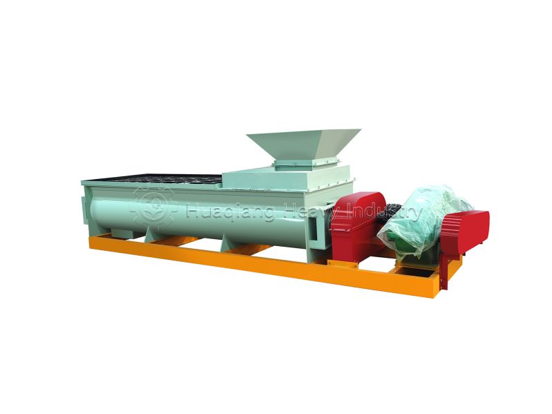
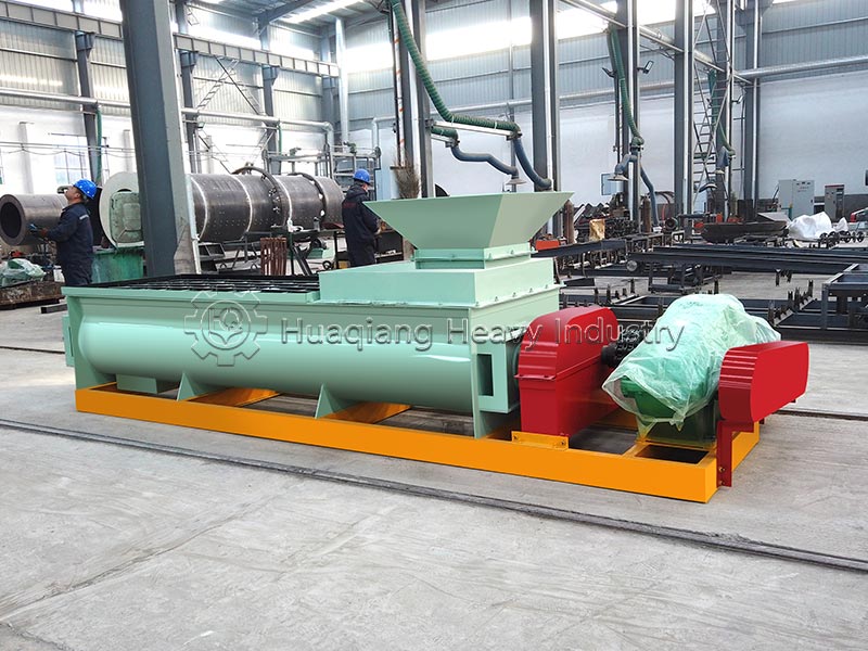
Double Shafts Mixer
Equipment Introduction
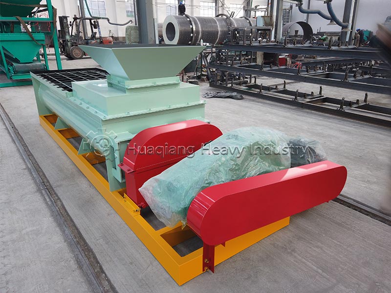
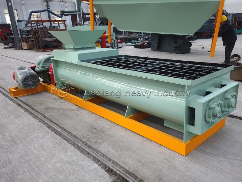
The double-shaft mixer, also known as a double-shaft paddle mixer, is a high-efficiency mixing device with two horizontal parallel main shafts as its core mixing elements. Its greatest advantage lies in its ability to achieve extremely high mixing uniformity (coefficient of variation ≤ 5%) in a very short time (typically 30–120 seconds/batch), and it is highly adaptable to differences in material specific gravity and particle size.
This equipment can be designed as a batch mixer for use in the feed, food, and pharmaceutical industries, or as a continuous mixer widely used in production lines for bulk materials such as fertilizers and building materials. The continuous mixer continuously receives material at the feed end, agitates and propels it with the propeller blades, and then discharges it immediately at the discharge end, combining the dual functions of mixing and short-distance conveying.
Equipment Structure
The double-shaft paddle mixer mainly consists of the following six systems:
- Body (Cylinder/Tank): It has a horizontal W-shaped or twin-circular structure, with two overlapping teardrop-shaped cavities inside. The shell is mainly welded from plates and shaped steel, ensuring a tight seal and preventing dust leakage. The cylinder and parts in contact with materials are often made of stainless steel (304, 316L) or carbon steel (Q235).
- Mixing Mechanism (Core Part): It consists of two horizontally arranged mixing shafts and multiple sets of specially angled blades mounted on the shafts. The two shafts are arranged parallel and symmetrically, with the blades arranged in a spiral pattern on the shafts. The blade material is selected from wear-resistant composite ceramics or wear-resistant alloys that are not prone to dust adhesion.
- Transmission System: It consists of a motor, reducer, transmission gears, sprockets, and chains. A cycloidal pinwheel reducer or a ZQ series reducer drives the two rotors to rotate in opposite directions. The sprocket and chain adopt a three-row chain structure, providing high transmission torque, smooth operation, and low wear.
- Feeding and Discharging Devices
1) Feed Inlet: Located at the top of the tank, material enters through this inlet.
2) Discharge Mechanism: The bottom adopts a full-length double-door structure for rapid discharge and minimal residue.
- Auxiliary Systems
1) Atomizing Humidification System: Atomizing nozzles are installed at the top for even spraying of water or nutrient solution.
2) Sealing Device: The shaft end uses a combination of labyrinth and packing seals for excellent double sealing performance.
3) Flying Knife Device: For fibrous materials, a high-speed flying knife can be added for cutting before mixing.
4) Variable Frequency Speed Control System: Operating parameters are flexibly adjusted according to material humidity and output.
- Frame Section
The entire frame is constructed from high-quality carbon steel plates and channel steel, with all working parts mounted and fixed on the frame.
Working Principle
- Power Transmission: The motor drives two main shafts to rotate synchronously in opposite directions at low speeds via a reducer and sprocket (industry average speed 30~46 r/min, SG600 is 36 r/min);
- Three-Dimensional Convection Mixing: The staggered blades propel the material, simultaneously generating three types of motion:
- Axial Motion: The blades spirally push the material forward and backward along the tank;
- Radial Convection: The counter-rotating dual shafts cause the material to surge upwards between the two shafts, forming a gravity-free suspension layer;
- Shearing and Crushing: The blades knead and break up clumps and coarse fibrous materials, eliminating the stratification of coarse and fine materials;
- Synchronous Humidification and Conditioning: During the material mixing process, the top spray system evenly sprays water to precisely control the material’s moisture content;
- Continuous Discharge: The material is mixed and humidified while being uniformly pushed axially to the discharge port, achieving continuous and uninterrupted operation.
Applicable Raw Materials
| Raw Material Category | Specific Raw Materials | Features / Remarks |
|---|---|---|
| Organic Fertilizer Raw Materials | Composted livestock and poultry manure (chicken manure, pig manure, cow manure, sheep manure, etc.) | High viscosity, high moisture, easy caking |
| Organic Fertilizer Raw Materials | Straw powder, mushroom residue, biogas residue | Fibrous organic materials |
| Organic Fertilizer Raw Materials | Peat‑moss, municipal sludge, kitchen waste | Organic waste materials |
| Chemical Fertilizer Raw Materials | Base fertilizer raw materials, compound fertilizer granules | Basic chemical fertilizer feedstock |
| Chemical Fertilizer Raw Materials | Inorganic salt raw materials, crushed powder from agglomerated feedstock | Recycled feedstock re‑processing |
| Chemical Fertilizer Raw Materials | Trace‑element fertilizer, special formula fertilizer raw materials | Special‑purpose fertilizer raw materials |
| Feed Raw Materials | Corn, wheat, rice, oats, sorghum, soybean meal and other grains | Conventional feed raw materials |
| Feed Raw Materials | Fish meal, bone meal and other high‑protein feedstock | High‑protein feed raw materials |
| Other Materials | Powder, granule, flake, block and miscellaneous materials | Handles multiple material forms |
| Other Materials | Viscous materials | Even mixing achievable with up to 30% liquid added |
| Other Materials | Fibrous materials | Fly‑cutter attachment is required |
| Moisture Adaptation Range | High‑moisture materials | Composted manure can be mixed directly without deep drying |
| Moisture Adaptation Range | Mixed dry & semi‑wet materials | Supports combined processing of dry and semi‑wet feedstock |
| Moisture Adaptation Range | Conventional medium‑moisture materials | Hard to cake or pile up |
Equipment Applications:
- Organic fertilizer production line: Core conditioning and mixing section after batching, standardizing carbon-nitrogen ratio and moisture content for pretreatment before fermentation and granulation (Huaqiang equipment’s main application scenario);
- Raw material premixing for compound fertilizer, BB fertilizer, and high-tower compound fertilizer production lines;
- Sludge and livestock manure harmless treatment, organic fertilizer fermentation pretreatment workshops;
- Wet mixing of building material dry mortar and clay brick making raw materials;
- Continuous mixing and conditioning of feed mills and chemical powders;
- Organic waste treatment sections in garbage and sewage treatment plants.
Equipment Parameters
| Type | Model | Core Parameters | Power Range |
|---|---|---|---|
| Continuous Type (SG Series) | SG400 | 8‑20 t/h, 46 rpm | 11 kW |
| SG500 | 15‑30 t/h, 42 rpm | 22 kW | |
| SG600 | 20‑35 t/h, 36 rpm | 30 kW | |
| Batch Type (WZL Series) | WZL‑1 | 1.0 m³, 300‑500 kg/batch | 7.5‑11 kW |
| WZL‑2 | 2.0 m³, 600‑1000 kg/batch | 11‑15 kW | |
| WZL‑3 | 3.0 m³, 1000‑1500 kg/batch | 18.5‑22 kW | |
| WZL‑5 | 5.0 m³, 1800‑3000 kg/batch | 30‑37 kW |
Application of the Equipment in the Production Line
In an entire organic fertilizer, compound fertilizer, or feed production line, the double-shaft paddle mixer is typically located after the crushing and screening process and before the granulation (or pelleting) process, serving as a core hub connecting the preceding and following stages:
- Homogenization of Ingredients: Receives various raw materials from the batching system (such as nitrogen, phosphorus, and potassium fertilizers, organic fertilizer powder, recycled materials, and trace elements), and uses high-intensity mixing to ensure uniform distribution of each component, guaranteeing stable nutrient content in the finished product.
- Moisture Control: During the mixing process, a spray system evenly sprays water, steam, or binders to adjust the material moisture content to the optimal range for granulation (typically 20%–30%), significantly improving the pelleting rate of subsequent pelletizers.
- Recycled Material Blending: Recycles unqualified particles (recycled materials) generated after drying, cooling, and screening into the new material, achieving a closed-loop cycle and reducing raw material waste.
- Continuous Operation Integration: The continuous double-shaft paddle mixercan be linked with belt scales and pelletizers to ensure continuous and stable operation of the production line, reducing fluctuations caused by batch changes.
Equipment Operation and Maintenance Methods
(I) Installation and Commissioning
- Foundation Installation: The equipment should be installed on a level concrete foundation and secured with anchor bolts.
- Installation Inspection: After installation, check for loose bolts in all parts and ensure the main unit’s door is secure.
- No-Load Test Run: The machine should be started under no-load conditions; starting with material is strictly prohibited. Check the rotation direction during no-load operation.
- Direction Confirmation: Start the main motor and check the rotation direction. If the direction is incorrect, stop immediately and adjust.
(II) Operating Procedures
- Pre-Start Inspection: Check that fasteners are secure, lubrication points have oil, and remove any debris that may obstruct operation. Check that the oil level in the bearing housing and reducer is adequate.
- Feeding Requirements: Large stones, iron blocks, etc., are strictly prohibited in the material to avoid damaging the mixing blades. No hard foreign objects larger than 5mm should enter the machine during operation.
- Operation Monitoring: Observe whether the motor runs smoothly and without abnormal noise. If any abnormal noises such as metallic clanging or friction are detected, stop the machine immediately for inspection and troubleshooting.
- Solid-Liquid Mixing: Run the machine first, then spray the liquid. After spraying, continue running the machine for 3-5 minutes to mix.
- Shutdown Procedure: Stop feeding material before stopping the machine. Stopping the machine while material is still present is strictly prohibited.
(III) Maintenance and Care Points
- Reducer Lubrication: The reducer must be filled with gear oil before production can begin. Replace the oil every 4 months thereafter. For initial use, change the lubricating oil after 300 hours of operation, and then every 2000-3000 hours thereafter.
- Bearing Lubrication: Replace the grease in the main shaft bearing housing every 3 months. Lubricate each bearing lubrication point once per shift.
- Bolt Tightening: Tighten the bolts every 24 hours to prevent loose bolts from causing changes in blade angle.
- Daily Cleaning: After long-term shutdown, thoroughly clean the material from the tank. Regularly clean any clumps of material from the bottom of the tank. 5. Regular Inspection: Regularly check the bending and deformation of the blade shaft, and replace it promptly if the blade tip is severely worn. Regularly check whether the atomizing nozzle is clogged.
Common Equipment Faults, Causes and Solutions
| Fault Phenomenon | Fault Cause | Standard Solution |
|---|---|---|
| Difficult motor startup, frequent overload tripping | Over‑feeding, material caking at bottom, jamming by large foreign objects | Stop machine immediately and clear caked materials inside trough; strictly follow start‑before‑feeding procedure; install feeding impurity‑removal sieve |
| Abnormal noise & heavy vibration during operation | Bearing oil shortage / damage, loose blade bolts, mis‑aligned shafts, gear wear | Add lubricant; fasten all blades and base bolts; calibrate double‑shaft parallelism; replace damaged bearings / gears |
| Persistent shaft‑end leakage and powder blowing | Worn sealing disc / oil seal; shaft scratched by hard adhered particles | Stop unit and clear accumulated shaft‑end materials; replace corrosion‑resistant sealing filler; regularly clean shaft attachments |
| Uneven material mixing, caked discharge | Severely worn blades, blocked spray nozzles with insufficient water supply, low rotating speed | Replace worn blades; unclog / replace atomizing nozzles; inspect rotating speed of motor and drive system |
| Abnormal overheating of bearing housing & reducer | Insufficient lubricant, deteriorated oil, long‑term over‑loading | Replenish specified lubricating oil; fully replace degraded oil; reduce single‑batch feeding weight |
| No water from spray system, uneven material moisture | Insufficient water pressure, clogged nozzles, water pipeline leakage | Install booster water pump; disassemble and clean spray nozzles; repair pipeline leakage points |
| Slow discharging speed, reduced output capacity | Offset blade angle, heavy material build‑up and caking inside trough | Recalibrate blade fixing angle; thoroughly clean residual materials on trough inner wall per shift |
Target Users of the Equipment
Due to its high uniformity, high efficiency, and strong adaptability, the twin-shaft paddle mixer is primarily intended for the following user groups:
- Medium to large-scale fertilizer enterprises: Production lines producing organic fertilizer and compound fertilizer with an annual output of over 30,000 tons require continuous, large-scale, and highly uniform premixing of raw materials.
- Feed processing plants: Enterprises producing livestock and poultry compound feed, aquatic extruded feed, and premixes, with strict requirements for mixing uniformity (CV≤5%).
- Building material production enterprises: Production lines for dry mortar, putty powder, tile adhesive, etc., requiring rapid and uniform mixing of cement, sand, and additives.
- Chemical and food enterprises: Scenarios sensitive to cross-contamination and requiring frequent formula changes; the large-opening discharge design of the double-shaft paddle mixereffectively reduces residue.
- Environmental protection and sludge treatment enterprises: Enterprises needing to mix and homogenize high-moisture materials such as sludge, straw, and conditioners in preparation for subsequent fermentation or incineration.
Installation Technical Requirements:
- The parallelism error of the double helix axis must be ≤0.4/1000, and the center offset of the two sprockets must not exceed 1°;
- All coupling connecting shafts must be strictly coaxial to prevent eccentric vibration;
- The entire machine body and drive base must be installed horizontally;
- After all anchor bolts and transmission components are tightened, manual rotation should be smooth and without jamming resistance;
- The water pressure in the spray pipeline must be stable, and the nozzles must be evenly distributed to ensure synchronous humidification of the material throughout the tank.
Double-shaft paddle mixers/Twin-shaft mixers are highly efficient core equipment in the modern powder and granular material mixing field. Through a unique mechanism of counter-rotating twin shafts, three-dimensional impeller scattering, and instantaneous homogenization of the weightless zone, they achieve mixing precision far exceeding that of traditional single-shaft equipment in a very short time. Whether for raw material premixing and humidification in continuous fertilizer production lines or for high-precision batching in the intermittent feed and food industries, this equipment meets the needs of large-scale industrial production with stable performance, low residue levels, and convenient maintainability. Proper installation accuracy, reasonable control of raw material moisture content and filling rate, and implementation of standardized maintenance are key to ensuring its long-term efficient operation.