
We are a professional manufacturer of organic fertilizer equipment and a customized service provider for fertilizer production lines
-
NO.313, Wanshan Road, Xingyang City, Zhengzhou City, Henan Province, China
Company Address
-
Call Us: +86-18703630069
(Sat - Thursday)
-
inquiry@hqhifertilizermachine.com
Our Email
Screw Conveyor

Equipment Introduction
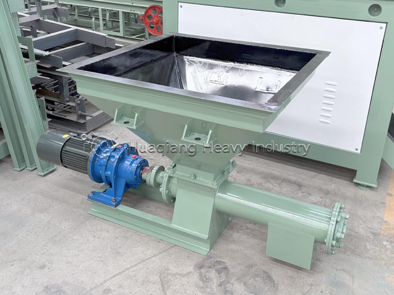
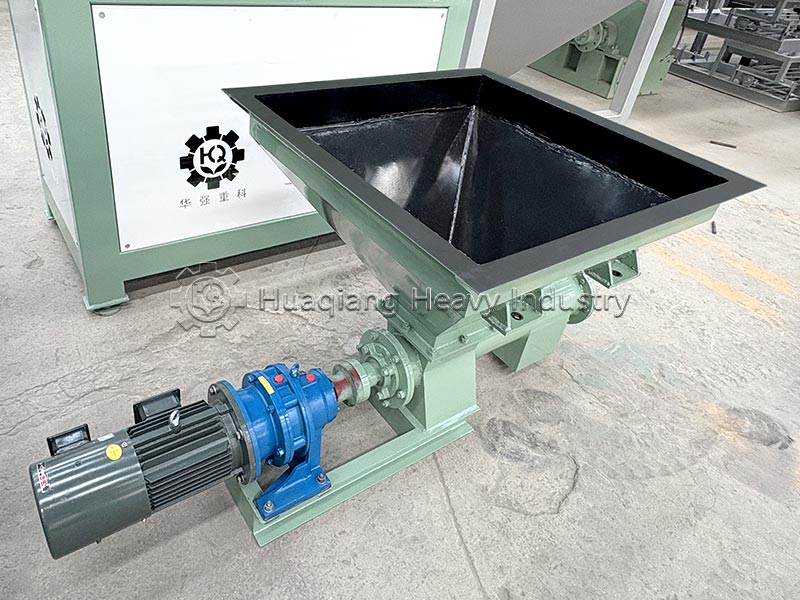
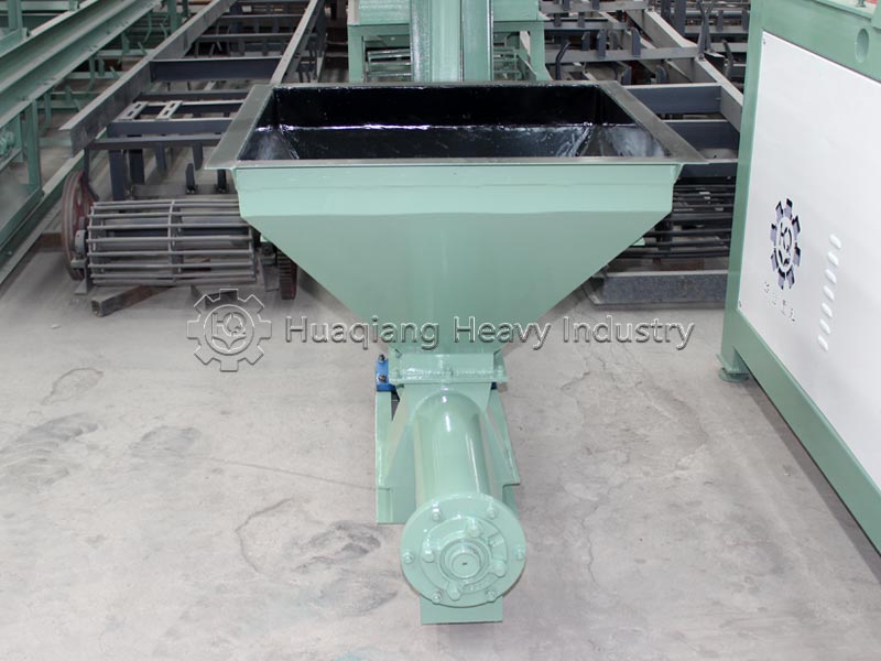
Screw conveyors are closed, continuous conveying equipment without traction components. The industry mainstream models are divided into two main series: LS (shafted U-type/tubular) and WLS (shaftless). They rely on rotating helical blades to push materials and are widely used in complete production lines for organic fertilizers and compound fertilizers. They are primarily used for short-distance closed transfer, quantitative feeding, and integrated mixing of powders and granules. Core Advantages (Suitable for the Fertilizer Industry)
- Fully Enclosed and Dust-Free: U-shaped cover/tube-type sealed structure ensures no dust leakage during the conveying of fertilizers and manure powder, meeting environmental protection standards.
- Compact Space and Flexible Layout: Can be arranged horizontally or at an angle of ≤20°, with multiple feeding and unloading points, suitable for batching silos and granulators for quantitative feeding.
- Combines Conveying and Mixing Functions: Simultaneously mixes materials during conveying, eliminating the need for separate mixing equipment.
- Low Cost and Small Footprint: Replaces belt conveyors for short-distance conveying, making it the preferred choice for small plant environments.
- Variable Frequency Precision Material Control: Enables stable quantitative batching, making it a core feeding device in fertilizer batching processes.
Structural Composition
The screw conveyor mainly consists of the following core components:
| Components | Function Description |
|---|---|
| Screw Shaft (Auger) | Composed of screw blades welded onto hollow shaft, it is the core working part generating axial thrust. Blade types include solid, ribbon and v‑flight, among which solid type is the most widely‑used. |
| Trough (Housing) | Material conveying channel, mainly U‑trough (open or covered) and tubular types. U‑trough facilitates maintenance while tubular version delivers better sealing performance. |
| Drive Unit | Combination of motor, reducer and coupling to provide rotary power. The reducer reduces rotating speed and increases output torque. |
| Bearing System | Head bearing and tail bearing support the screw shaft. Hanger bearings shall be added for long‑length machines, yet they hinder material flow, so minimize their quantity for long‑distance designs. |
| Inlet & Outlet | Feed inlet is normally arranged at tail end, and discharge outlet is on the same side as drive unit. This keeps screw shaft under tension and improves stress condition. |
Working Principle
The working principle of a screw conveyor can be figuratively described as “a non-rotating nut moving along a rotating screw in translational motion.”
Specifically, when the screw shaft begins to rotate under the drive of a motor, material enters the casing through the feed inlet. Due to the material’s own weight and the friction between the material and the casing wall, the material does not rotate with the screw blades. Under the continuous pushing force of the rotating screw blades, the material is propelled forward along the bottom of the casing and finally discharged from the outlet.
For longer conveyors, the movement of material at the intermediate bearing is achieved by the thrust of the material moving behind it. During the conveying process, the material undergoes a purely sliding motion.
Suitable Materials
Screw conveyors have a wide range of applications, but they have specific requirements for the materials they handle.
✔️ Suitable Materials:
Mainly suitable for conveying loose materials such as powders, granules, and small lumps. Specific examples include: cement, fertilizer, grain, flour, coal powder, ash, and sand. For sticky or easily entangled materials (such as sludge, biomass, and garbage), a shaftless screw conveyor should be selected.
❌ Unsuitable Materials:
Screw conveyors are not suitable for conveying materials that are easily perishable, excessively sticky, or prone to caking. They are also unsuitable for conveying large pieces of material, materials containing many fibrous impurities, or highly abrasive materials, to avoid blockages and excessive wear.
Applications in Fertilizer Production Lines
Standard configuration for the three core sections of the entire production line: batching, granulation, and fine powder recovery:
- Batching Section (Core Purpose): A screw feeder below the silo provides quantitative feeding, precisely proportioning various organic and chemical fertilizer powders, replacing manual feeding;
- Granulation Feeding and Conveying: The discharge screw from the mixer feeds the material at a uniform speed into the disc/drum granulator, stabilizing the granulation feed flow;
- Fine Powder Recycling: Fine powder generated during screening is returned to the mixer via a short screw for secondary granulation;
- Coating Support: A powder coating agent (talc) is quantitatively conveyed to the inside of the coating machine;
- Short-Distance Transfer: Small quantities of material are conveyed in a closed system between silos and at the front end of the drying process.
Supporting Process Link: Raw Material Silo → LS Screw Quantitative Batching → Mixer → LS Screw → Granulator → Dryer → Cooler → Screening Machine → Fine Powder Screw Return → Mixer
Common Faults and Troubleshooting
Screw conveyors may experience various faults during operation. The following are common problems, their causes, and solutions:
| Common Fault | Main Cause | Treatment Method |
|---|---|---|
| Difficult startup | 1. Reducer malfunction; 2. Improperly‑selected undersized motor power; 3. Material blockage at hanger bearing | 1. Inspect and repair the reducer; 2. Recalculate and replace motor with proper power; 3. Clear accumulated material at hanger bearing |
| Dust leakage | 1. Unreasonable shaft‑end sealing or damaged sealing parts; 2. Damaged or improperly‑installed sealing strips on flange joint and access door | 1. Improve sealing structure or replace damaged sealing components; 2. Re‑install or replace sealing strips |
| Material blockage at hanger bearing | Large bearing body, small flow cross‑section after installation causing material accumulation | 1. Optimize structural design of hanger bearing; 2. Regularly clean accumulated material at this position |
| Screw shaft fracture | 1. Excessive torque caused by overload or material blockage; 2. Defects or fatigue failure of screw shaft itself | 1. Avoid overload and clear blockage timely; 2. Install brand‑new screw shaft |
| Scraping against housing | 1. Bending deformation of screw shaft; 2. Severe wear of intermediate hanger bearing resulting in screw shaft sagging | 1. Straighten or replace screw shaft; 2. Replace worn bearing and adjust to correct position |
| Fracture of connecting bolt | Connecting bolts at head joint bear maximum torque | Adopt high‑strength bolts at head joint; three‑bolt connection is optional when necessary |
Operation and Maintenance
While screw conveyors are relatively easy to maintain, the following points directly impact equipment lifespan and operational stability:
- Lubrication Management: Regularly lubricate bearings, gears, chains, and other transmission components.
- Blade Inspection: Periodically check the wear of the screw blades. Repair or replace severely worn blades promptly.
- Overloading Prohibited: Do not overload the conveying capacity; otherwise, material will not be able to discharge, leading to screw shaft bending and casing damage.
- Temperature Monitoring: Under high-temperature conditions, ensure the casing expands and contracts freely to prevent thermal expansion and jamming.
- Abnormal Handling: If a harsh noise is emitted during operation, immediately stop the machine for inspection, eliminating faults such as blade interference with the casing or bearing damage.
- Shutdown Cleaning: After conveying viscous or easily agglomerated materials, clean the trough promptly to prevent residual material from hardening and causing jamming.