
We are a professional manufacturer of organic fertilizer equipment and a customized service provider for fertilizer production lines
-
NO.313, Wanshan Road, Xingyang City, Zhengzhou City, Henan Province, China
Company Address
-
Call Us: +86-18703630069
(Sat - Thursday)
-
inquiry@hqhifertilizermachine.com
Our Email
Vertical Disc Mixer
Equipment Introduction
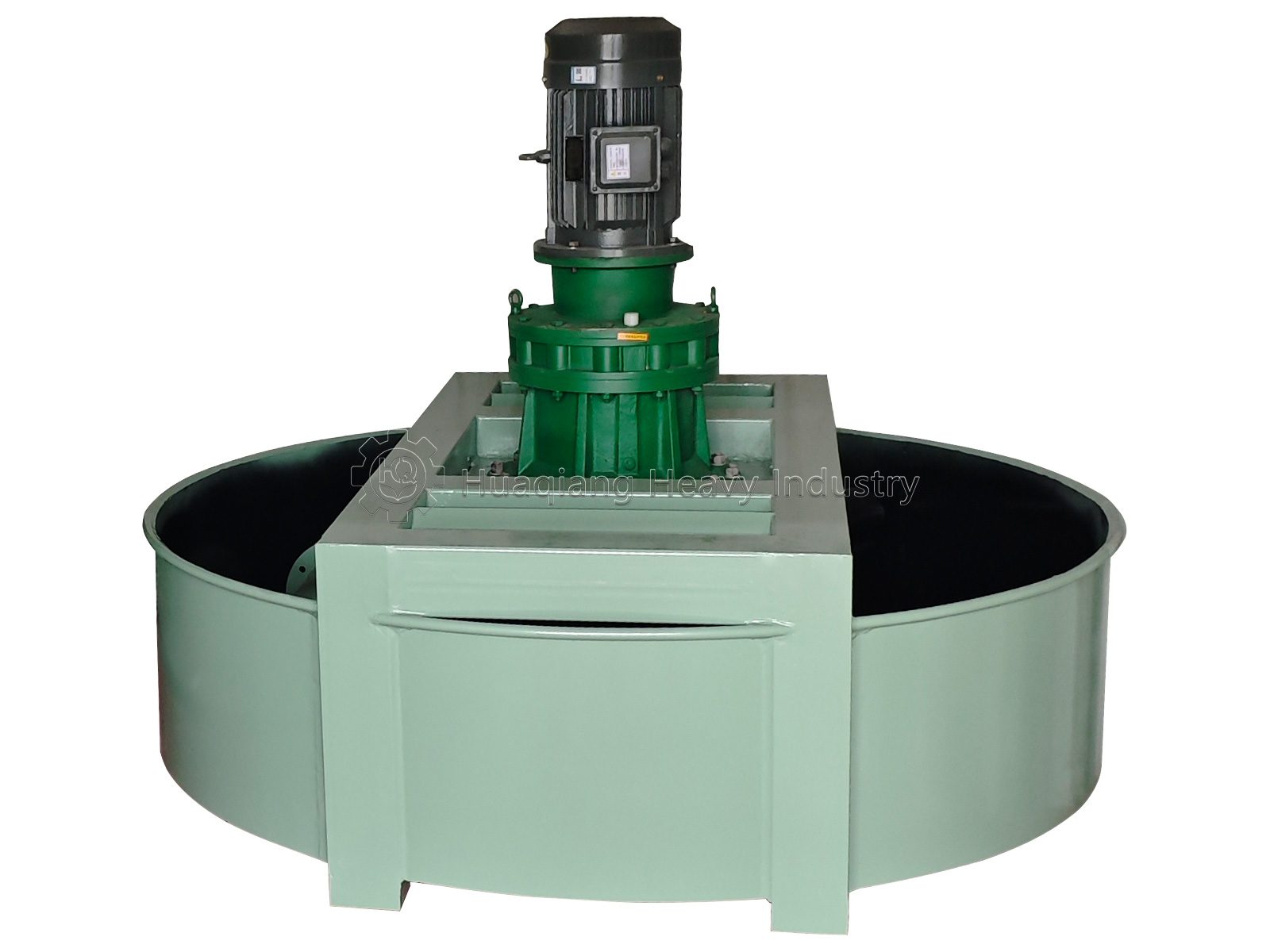
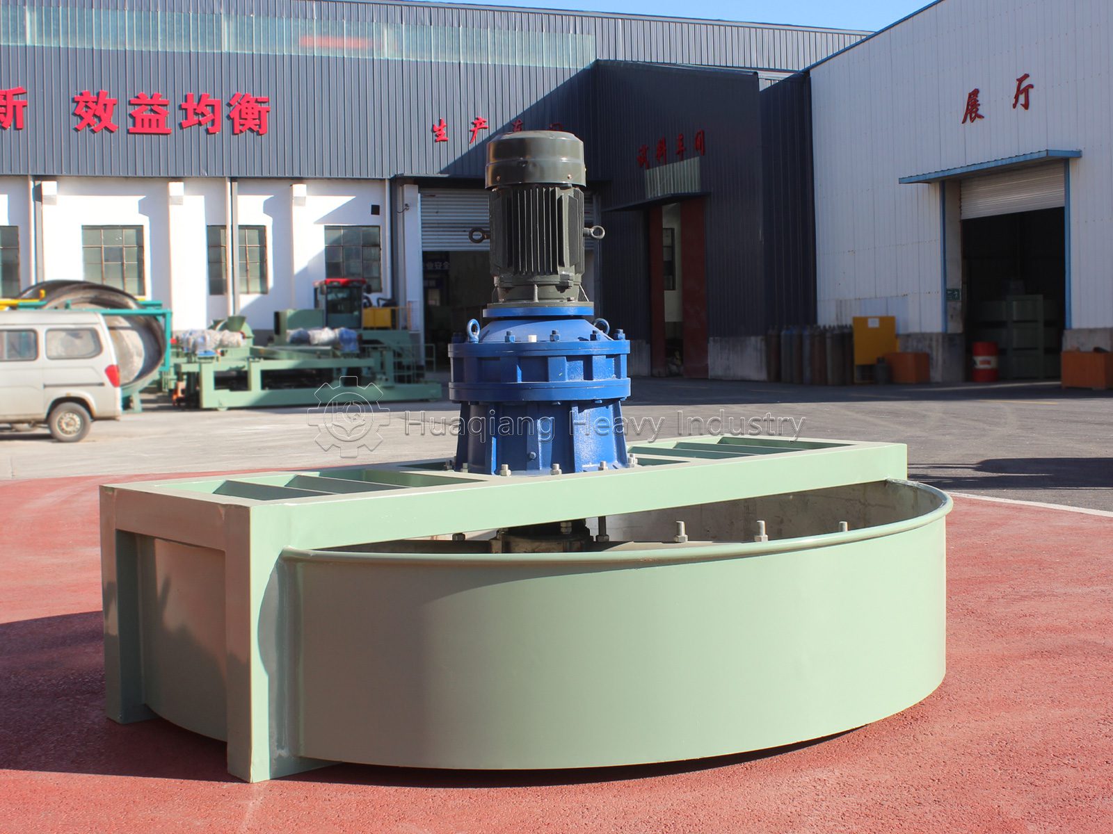
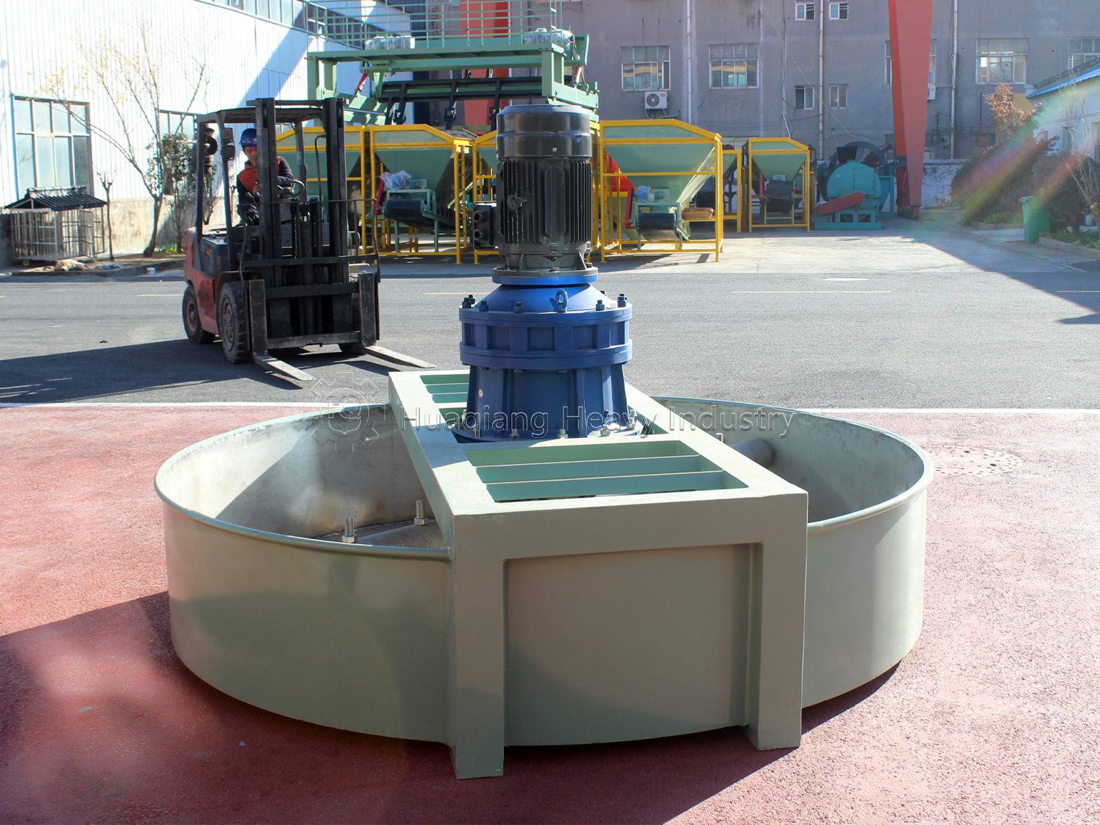
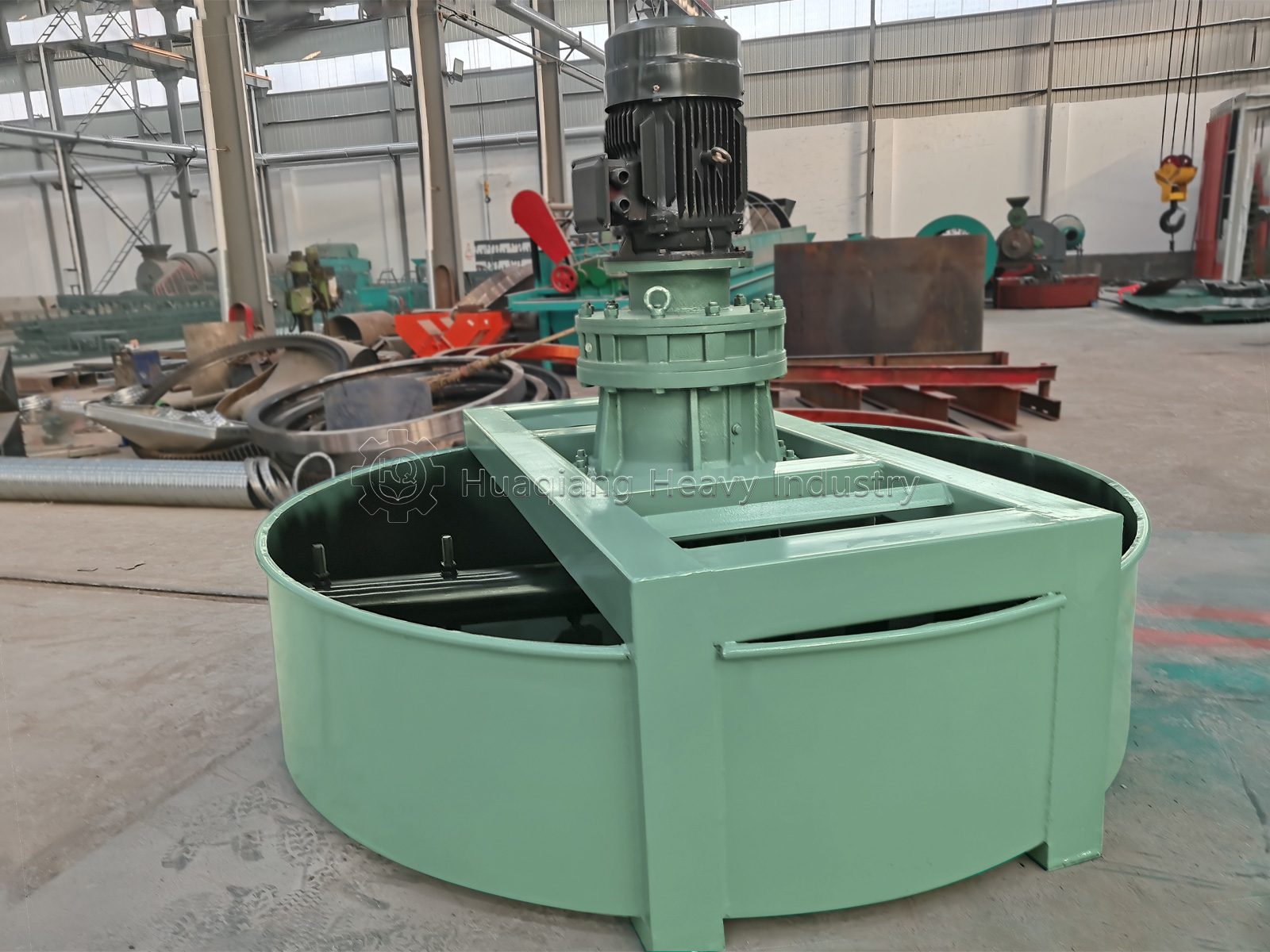
A vertical disc mixer, also known as a vertical disc mixer or disc agitator, is a device that uses a vertical disc as a container and mixes materials through high-speed tumbling of mixing teeth/arms. The equipment consists of a mixing disc, discharge port, mixing arms, frame, gearbox, and transmission mechanism.
Vertical disc mixers are widely used raw material mixing machinery in industries such as organic fertilizer, compound fertilizer, chemicals, mining, and building materials. Their core advantages lie in their small footprint, compact structure, suitability for small to medium production capacity and high-moisture/viscous materials, and especially suitability for small to medium-sized production lines with limited space. This equipment boasts a long service life, energy efficiency, small size, fast mixing speed, and continuous operation.
Compared to horizontal mixers, vertical disc mixers, with their flexibility, compact size, low residue, and ease of cleaning, have become a highly cost-effective supplementary option to large horizontal mixers.
Equipment Structure Composition
The entire machine is divided into three main parts: the frame assembly, the transmission connection assembly, and the mixing assembly. It is equipped with a feed inlet, bottom discharge door, lubrication system, and sealing components:
- Frame Assembly
1) Material: High-quality carbon steel plate and channel steel welded as a whole, after aging stress relief treatment;
2) Function: Bears all working parts including the motor, reducer, and mixing disc; pre-drilled mounting holes at the bottom;
3) Features: High rigidity, low vibration, lightweight design, and simple on-site installation.
- Transmission Connection Assembly
1) Drive Motor: Three-phase industrial asynchronous motor, standard configuration with optional frequency conversion speed regulation;
2) Cycloidal Pinwheel Reducer: Compact structure, large reduction ratio, overload resistant, providing stable torque to the main shaft;
3) Pin Coupling (Nylon Pin): Buffer and dampen vibration, easy to disassemble and assemble; only the pin needs to be replaced after damage, resulting in low maintenance costs;
4) Main Shaft Seal: Labyrinth + packing double seal to prevent fine powder from entering the bearings and causing wear. 3. Mixing Assembly (Core Mixing Unit)
1) Circular Mixing Pan: Carbon steel body, lined with polypropylene/304 stainless steel wear-resistant lining; pan wall height increases with model.
2) Mixing Main Shaft: Solid, thickened alloy steel main shaft, running through the center of the pan.
3) Multi-layer Mixing Blades (Impellers): High-chromium wear-resistant alloy material, 2-3 layers staggered, 5-10mm gap between blade tips and pan bottom to prevent material accumulation.
4) Feed Inlet: Top grid feed; can be equipped with iron removal/screening devices to intercept hard impurities.
5) Bottom Discharge Port: Electric/pneumatic discharge gate, compatible with belt conveyors and granulators.
6) Inspection and Cleaning Door: Side opening for easy cleaning of clumps in the pan and replacement of mixing blades.
Application scope of equipment
Vertical disc mixers are used across a variety of industries:
| Application Field | Specific Applications |
|---|---|
| Fertilizer Industry | Proportioning and mixing of organic fertilizer, bio‑organic fertilizer, compound fertilizer (NPK) and BB fertilizer raw materials |
| Chemical Industry | Proportioning and mixing of dry powder and granular chemical raw materials |
| Building Material Industry | Mixing of cement, refractory materials, rare earth and other powdery materials |
| Feed Industry | Mixing of straw powder, grain powder and feed raw materials |
| Environmental Protection | Thermal power plant dust treatment and harmless treatment of organic waste |
| Metallurgy & Mining | Proportioning and mixing of ore powder and metallurgical auxiliary materials |
Working Principle of the Equipment
The working principle of the vertical disc mixer can be summarized as a combination of “centrifugal dispersion” and “gravity diffusion”:
- Power Transmission: After the motor starts, the speed is reduced and the torque increased by a cycloidal pinwheel reducer, and the power is transmitted to the vertical main shaft through a pin coupling.
- Material Movement: The material falls into the rotating disc from the top feed inlet. The mixing main shaft drives the impeller/mixing teeth to rotate. Under the action of centrifugal force, the material is pushed against the disc wall, and at the same time, it is turned up from the bottom by the lifting plates, forming a continuous circulating flow of material that rises along the disc surface, is dispersed, and falls back to the center.
- Homogeneous Mixing: In this process, high-frequency collisions, interpenetration, and diffusion occur between material particles, allowing components with large differences in specific gravity (such as light organic fertilizer powder and heavy chemical fertilizer granules) to be fully interwoven.
- Discharge: The uniformly mixed material is discharged from the bottom discharge outlet under the action of gravity, entering the next process (such as granulation or packaging). By adjusting the disc tilt angle (usually 30°–60°) and the spindle speed, the residence time of the material in the disc (generally 3–5 minutes) can be controlled, thereby precisely controlling the mixing uniformity.
Raw Materials for the Equipment
This equipment is suitable for processing materials in various forms, but has certain requirements regarding the characteristics of the raw materials:
- Form: Powdered, fine granular, and lightweight flake materials are best.
- Moisture Content: The suitable range is 20%–30%. Too high a moisture content (>35%) can easily lead to sticking to the walls and clumping; too low a moisture content will result in more dust.
- Particle Size: The raw materials should be pre-crushed and screened to prevent large stones, iron blocks, woven bags, and other hard foreign objects from entering, thus preventing damage to the impeller and main shaft.
- Common Raw Materials: Fermented and decomposed livestock and poultry manure, straw powder, nitrogen, phosphorus, and potassium fertilizers, recycled materials (unqualified particles after screening), bentonite, humic acid, functional microbial agents, etc.
Equipment Operation and Maintenance Methods
(I) Installation and Commissioning
- Foundation Installation: The equipment should be installed on a level concrete foundation. Due to its reasonable design and minimal vibration, a particularly strong concrete foundation is not required. The foundation must be firm and level to prevent bolts from loosening due to vibration during operation.
- Installation Inspection: After installation, check all bolts for looseness. The cable tray should be leveled, and the semi-cable tray columns should be verticalized.
- No-Load Test Run: The machine should be started under no-load conditions; starting with material is strictly prohibited. Run the machine under no-load for 1-2 minutes and observe whether the main shaft rotation is correct (counterclockwise is the normal direction).
- Direction Confirmation: Start the main motor and check whether the rotation direction is correct. If the direction is incorrect, stop immediately and adjust.
(II) Operating Procedures
- Feeding Requirements: Large stones, iron blocks, etc., are strictly prohibited in the material. The feeding speed should be strictly controlled to ensure that the material stays in the disc for no less than 3-5 minutes.
- Operation Monitoring: Pay attention to whether the motor runs smoothly and whether the temperature rise is normal. If excessive vibration is detected in the equipment, it may be due to uneven material distribution, uneven wear of the mixing blades, or an unstable equipment foundation. The machine should be stopped immediately for inspection.
- Shutdown Procedure: Before stopping the machine, feeding should be stopped first. Stopping the machine while material is still present is strictly prohibited.
(III) Maintenance and Care Points
- Reducer Lubrication: Gear oil must be added to the reducer before production begins. Replace the oil every 4 months thereafter.
- Bearing Lubrication: Replace the grease in the main shaft bearing housing every 3 months. Regularly check the lubrication points.
- Discharge Mechanism Lubrication: Lubricating oil should be frequently applied to the discharge gate lever.
- Daily Cleaning: After each shift, remove all adhering and residual material from the mixing disc. Wipe the control panel and equipment surface with a cloth to keep the equipment clean. Prevent water from entering the motor, electrical control box, etc.
- Regular Inspection: Regularly inspect the mixing blades and shaft to prevent severe wear from affecting mixing performance. Pay special attention to checking the flatness of the chassis and the wear of the mixing teeth. 6. Sealing maintenance: The seal between all mating surfaces must be tight.
Common Equipment Faults and Solutions
| Fault Phenomenon | Main Causes | Solutions |
|---|---|---|
| Uneven mixing & severe local agglomeration | Raw material moisture too high (>60%); severely worn mixing blades; improper blade angle; over‑feeding; insufficient mixing retention time | Dry high‑moisture raw materials, control moisture at 30%‑50%; add powder conditioner; replace blades when wear exceeds 5mm; adjust blade angle to 42°‑45°; control feeding speed; extend mixing retention time over 3‑5 minutes |
| Severe vibration and abnormal noise | Loose anchor bolts; excessive shaft misalignment between reducer and motor; rotor unbalance caused by material sticking; bearing wear & insufficient lubrication | Tighten anchor bolts and add anti‑vibration gaskets; re‑calibrate shaft alignment within 0.2mm; clean sticking materials to keep rotor balance; inspect bearings, replace damaged parts and refill lubricant |
| Disc jumping | Loose disc guard plate; foreign objects jammed between disc and housing; damaged radial bearing; excessive clearance of thrust bearing; excessive installation level deviation | Fasten and flatten loose guard plate; remove jammed foreign objects; replace damaged radial bearing; adjust thrust bearing clearance; re‑calibrate disc level and concentricity for stable operation |
| Blockage at inlet & outlet | Oversized raw material particles & large impurities; sticky wet material sticking at discharge port; excessive feeding speed and material accumulation | Install screen at feed inlet to sieve out impurities over 50mm; clean sticky materials at outlet; install anti‑sticking coating; adjust conveyor speed for uniform feeding; set outlet inclination ≥35° to improve material flow |
Equipment Application and Layout in the Production Line
- Standard Process Flow: Automatic Batching System → Vertical Disc Mixer → Belt Conveyor → Granulator (Extrusion/Drum Granulation);
- Functional Positioning: Homogenization pretreatment before granulation, unifying the moisture and nutrient ratios of materials, significantly improving granulation pelleting rate and particle strength, and reducing nutrient deviation in finished fertilizer;
- Line Compatibility:
1) Small-scale organic fertilizer line with an annual output of 10,000 to 50,000 tons: Single PJ1600/PJ1800 unit independently;
2) Medium-scale production line with an annual output of 100,000 to 300,000 tons: Two PJ2200/PJ2500 units connected in parallel to achieve continuous and uninterrupted mixing;
- Automated Linkage: Can be equipped with PLC automatic batching, pneumatic unloading, and online dust removal systems to achieve a fully unattended mixing section.
Target Users of the Equipment
Vertical disc mixers are particularly suitable for the following user groups due to their high cost-effectiveness and ease of maintenance:
- Small and medium-sized organic fertilizer plants: Production lines with an annual output of 10,000-30,000 tons of powdered or granular organic fertilizer, where space is limited and budgets are controllable.
- Start-up fertilizer companies: Low investment threshold, rapid start-up, and short payback period.
- Bio-organic fertilizer/microbial fertilizer companies: The gentle tumbling mixing method minimizes damage to the activity of functional microbial agents, suitable for microbial inoculation and activation processes.
- Compound fertilizer/NPK production companies: As a premixing device in the batching stage, achieving uniform proportioning of various raw materials.
- Feed processing plants: Used for mixing feed raw materials such as straw powder and grain powder.
- Building materials and chemical companies: Mixing and blending materials such as dry mortar and refractory materials.
Equipment Parameters
| Model | Disc Diameter (mm) | Wall Height (mm) | Speed (r/min) | Power (kW) | Capacity (t/h) | Overall Dimension (mm) | Weight (kg) |
|---|---|---|---|---|---|---|---|
| PJ1600 | 1600 | 400 | 12 | 5.5 | 3‑5 | 1700×1700×1368 | 1200 |
| PJ1800 | 1800 | 400 | 11 | 11 | 4‑6 | 1900×1900×1600 | 1400 |
| PJ2200 | 2200 | 500 | 11 | 15 | 6‑10 | 2300×2300×1650 | 1668 |
| PJ2500 | 2500 | 550 | 11 | 15 | 10‑16 | 2600×2600×1750 | 2050 |
Vertical disc mixers, with their simple structure, small footprint, low energy consumption, convenient maintenance, and low investment threshold, have become a practical core piece of equipment in small and medium-sized fertilizer production lines and the mixing of powdered materials in various industries. A proper understanding of their working principles, strict adherence to operating procedures, and standardized maintenance can effectively reduce failure rates, extend equipment lifespan (up to 8-10 years with proper maintenance), and ensure the stability of finished product quality. For production enterprises with limited budgets, compact spaces, and moderate requirements for mixing uniformity, vertical disc mixers are an ideal alternative to manual mixing or expensive horizontal equipment.