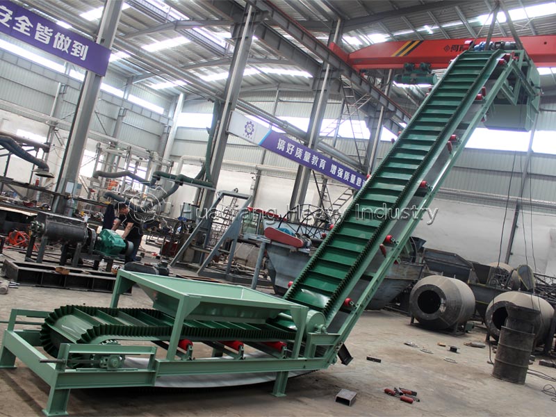
In fertilizer production workshops, belt conveyors bear the heavy responsibility of raw material feeding, semi-finished product transfer, and finished product packaging. However, fertilizer materials often contain moisture, viscosity, and irregular particles, which easily cause conveyor belt slippage and deviation, resulting in minor spillage and wear, or even belt tearing or machine shutdown. This article, starting from operational details and based on industry-standard technical specifications, systematically explains the setting basis for three core parameters: tilt angle limit, idler spacing, and automatic correction device, providing an operational guide for on-site maintenance and equipment selection.
Tilt Angle Limitation: The Underlying Physical Boundary for Anti-slip
The conveyor belt tilt angle is the primary parameter determining whether materials can be transported stably. Slippage essentially occurs when the component of the material’s gravity along the belt direction exceeds the static friction between the belt and the rollers. For ordinary smooth conveyor belts, when conveying conventional compound fertilizers or organic fertilizers, the maximum permissible tilt angle should not exceed 18°–20°; if the material moisture content is higher than 15% or the particle surface is smooth (such as urea), the tilt angle should be further reduced to ≤16°. When a large inclination angle is necessary, herringbone or diamond-patterned conveyor belts should be selected, which can increase the friction coefficient by 30%–50% and allow for an inclination angle of 25°–28°. However, in this case, the hardness of the rubber coating layer of the drive roller must be increased simultaneously (Shore hardness 65–75 is recommended) and a gravity tensioning device must be installed to ensure no slippage during start-up and shutdown.

Idler Spacing: The Mechanical Fulcrum for Load Bearing and Belt Misalignment Idler spacing directly affects the belt’s sag, lateral stiffness, and belt misalignment sensitivity. Specifications require: the spacing of the upper idlers (load-bearing section) is generally 1.0 m–1.2 m, and the spacing of the lower idlers (return section) is 2.0 m–3.0 m. When the belt width is greater than 1200 mm or the load per unit length exceeds 50 kg/m, the upper idler spacing should be increased to 0.8 m–1.0 m to reduce lateral belt sway caused by material impact. A set of buffer idlers must be installed below the material drop point, with a spacing not exceeding 0.4 m. The rubber ring hardness of the buffer idlers should be lower than that of ordinary idlers (Shore Type A 55-60) to absorb impact energy and prevent belt misalignment due to uneven force on both sides caused by local deformation. It is particularly important to note that a set of self-aligning idlers should be added within 3 meters of the head and tail rollers, with a spacing 20% shorter than the conventional section, to enhance the corrective response capability at the beginning and end.
III. Automatic Correction Device: Active Correction and Intelligent Intervention Simply relying on manual adjustment of rollers or guide rollers is no longer sufficient to meet the requirements of continuous production. Modern fertilizer conveyor lines should be equipped with automatic correction devices as standard. The mainstream solutions fall into three categories: Mechanical self-aligning idler sets, which rely on the pressure exerted on the lateral guide rollers when the belt deviates, causing the idler frame to rotate around its vertical axis and generate additional frictional torque, automatically pushing the belt back to the center. This is suitable for medium-to-low speed conditions with a belt width ≤1000 mm and a speed ≤2.5 m/s. Hydraulic automatic belt alignment systems, which detect the belt edge position and drive hydraulic cylinders to adjust the roller angle, have a response time ≤3 seconds and a large correction force, suitable for high-speed, heavy-load lines with a belt width ≥1200 mm and a speed ≥3.15 m/s. Pneumatic or electrically controlled alignment devices, which use photoelectric or ultrasonic sensors to monitor belt offset in real time. When the offset exceeds 3% of the belt width, an air valve is activated to push the idler set for correction, with accuracy controllable within ±5 mm. Regardless of the device used, its installation position should preferably be located at the first third of the carrying section and the end of the return section, with at least one set every 20–30 meters to ensure multi-point coordinated control over long-distance transport.
Supporting Maintenance Standards and Operational Guidelines
In addition to the three mandatory indicators mentioned above, anti-slip and anti-deviation measures also require adherence to daily inspection procedures: Measure the wear of the roller rubber coating weekly; replace it immediately when the remaining thickness is less than 70% of the original thickness; check the flatness of the belt joint monthly; the lateral error at the joint must not exceed 0.5 mm; before each startup, a 2-minute no-load test run must be performed to observe whether the belt runs stably within ±10 mm of the roller center. Forcibly adjusting the tension screw under belt load is prohibited, as is cleaning the belt surface with water or oil—these operations will drastically reduce the coefficient of friction and corrode the rubber layer, directly undermining the design foundation of the tilt angle and deviation correction.
The belt conveyor, often described as the “blood vessel” of a fertilizer plant, plays a critical role that extends far beyond material transfer. Its anti‑slip and deviation control performance directly affects the uptime and product quality of the entire production train. While the core fertilizer equipment—such as the fertilizer granulator machine, fertilizer crusher and mixer, fertilizer dryer and cooler, and automatic fertilizer packing machine—are essential for processing and packaging, they all rely on a well‑designed fertilizer conveyor series to maintain a steady, uninterrupted material flow. The belt conveyor connects every unit, from raw material intake to finished product discharge, and its correct tilt angle, idler spacing, and automatic correction device ensure that even sticky, high‑moisture fertilizers are transported smoothly without spillage or belt damage. While the industrial fertilizer machine price often focuses on the major processing units, underestimating the conveyor system can lead to frequent downtime, increased maintenance costs, and compromised product consistency. By adhering to the technical specifications outlined above—proper angle limits, scientifically spaced idlers, and responsive auto‑tracking systems—operators can achieve a reliable, low‑wear conveying line that integrates seamlessly with the rest of the plant. In short, a robust belt conveyor system is not an accessory but a foundational investment that safeguards production continuity, reduces material waste, and ultimately contributes to the long‑term profitability of any fertilizer manufacturing facility.
In summary, the tilt angle defines the inherent conditions for anti-slip, the idler spacing establishes the geometric stiffness of operation, and the automatic correction device provides dynamic fault tolerance. These three are not independent parameters but rather a coupled system engineering: the larger the tilt angle, the higher the requirements for idler spacing and deviation correction sensitivity. Understanding and strictly adhering to these numerical boundaries are essential to ensuring the long-term stable and efficient operation of the fertilizer conveyor line.