
We are a professional manufacturer of organic fertilizer equipment and a customized service provider for fertilizer production lines
-
NO.313, Wanshan Road, Xingyang City, Zhengzhou City, Henan Province, China
Company Address
-
Call Us: +86-18703630069
(Sat - Thursday)
-
inquiry@hqhifertilizermachine.com
Our Email
Large Angle Belt Conveyor
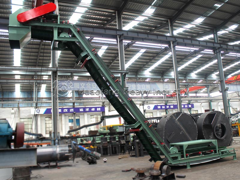
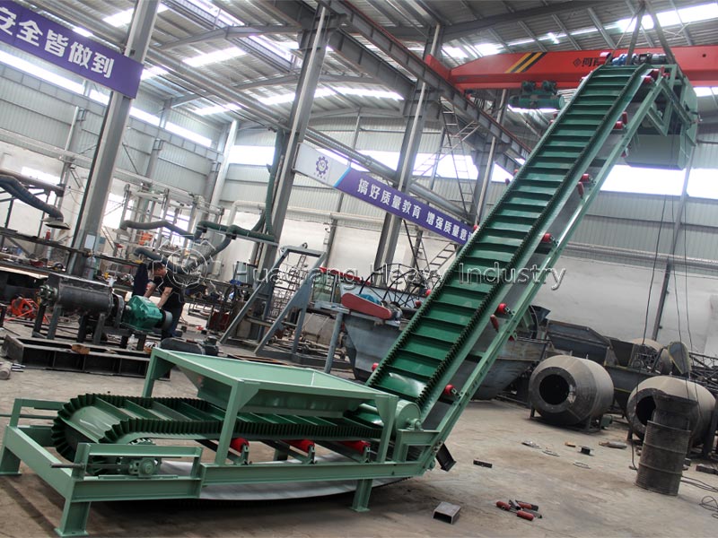
Equipment Introduction
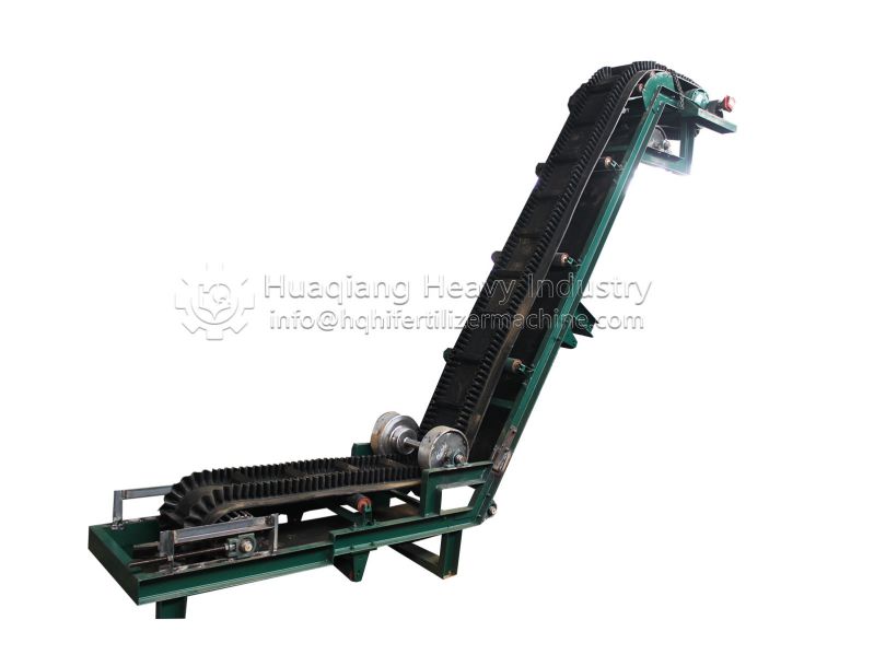
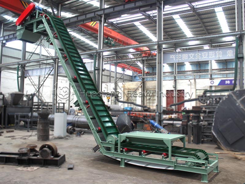
The large-angle belt conveyor is a special continuous conveying equipment that breaks through the limitations of ordinary belt conveyors. It relies on a cassette-type hopper composed of corrugated rubber sidewalls and transverse partitions to solve the problems of conventional belts having a maximum inclination angle of only 15° and the tendency for highly moist materials to slip and spill. The conveying angle is adjustable from 0° to 90°, enabling near-vertical material lifting.
(I) Core Advantages
- Significantly Reduced Factory Footprint: For the same lifting height, the horizontal projection length is reduced by over 60% compared to ordinary conveyor belts, eliminating the need for long ramp construction and making it suitable for low-ceilinged, compact organic fertilizer workshop renovations;
- Excellent Adaptability to High-Moisture Materials: The box-shaped enclosed hopper can stably transport wet livestock and poultry manure with a moisture content of 20%~45%, with no lateral leakage or backflow;
- Low Particle Breakage Rate: Flexible rubber bearing capacity reduces fertilizer breakage by 80% compared to bucket elevators, ensuring the appearance of finished particles;
- Lower Energy Consumption and Simpler Maintenance: The installed power is less than that of bucket elevators for the same production capacity. Standardized idler rollers and sweepers reduce maintenance difficulty;
- Environmentally Friendly Sealed Configuration: The entire machine is equipped with a fully enclosed dust cover, preventing dust spillage during the transport of powdered organic fertilizer and meeting environmental protection standards;
- Flexible Layout: Can be configured in Z-shape or S-shape. The machine features a straight-up, vertical layout with integrated horizontal sections at the head and tail, allowing direct connection to crushers, dryers, and silos.
(II) Core Comparison with Conventional Conveying Equipment
| Comparison Item | Large‑angle Sidewall Belt Conveyor | Ordinary Trough‑shaped Belt Conveyor | Bucket Elevator |
|---|---|---|---|
| Max Conveying Inclination | 90° Vertical | ≤15° | 90° Vertical |
| Applicable Material Moisture Content | 0~45% high‑humidity manure fertilizer | ≤25% dry granules | ≤30% medium humidity |
| Material Breakage Degree | Extremely low (flexible conveying) | Low | Relatively high (steel bucket impact) |
| Floor Horizontal Occupation | Minimum | Large | Medium |
| Main Operation & Maintenance Cost | Low (local belt repair) | Lowest | High (chain & bucket wear) |
Structural Composition
The structure of a steep-angle belt conveyor can be divided into two main categories: “general-purpose components” and “special-purpose components for steep-angle conveyors.” It features a high degree of modularity, with key components interchangeable with those of general-purpose belt conveyors.
1.Core Special-Purpose Component – Corrugated Sidewall Conveyor Belt
This is the core feature that distinguishes a steep-angle belt conveyor from ordinary belt conveyors. It consists of a three-layer structure integrally formed through a hot vulcanization process.
| Structure Layer | Function Description |
|---|---|
| Base Belt | Made of rubber canvas or steel‑cable core rubber belt. It provides tensile strength and longitudinal flexibility, serving as the skeleton of the conveyor belt. |
| Corrugated Sidewall (Skirt Edge) | Vertical corrugated rubber edges on both sides to prevent material side spillage. It can freely compress and expand when passing over pulleys, and return to upright state on straight sections. |
| Transverse Cleat (Baffle) | T‑type or C‑type rubber cleats arranged at certain intervals. Together with sidewalls, they form box‑shaped hoppers to carry materials and prevent sliding‑down. |
2.General-Purpose and Compatible Components
| Components | Function Description |
|---|---|
| Drive Unit | Motor + Reducer + Back‑stop device, provides power for the whole machine. For large‑angle working conditions, back‑stop device shall be equipped to prevent belt reverse rotation caused by material gravity during shutdown. |
| Drive Pulley | Coated rubber surface to increase friction, core component for power transmission; higher rubber coating requirement for large‑angle conditions. |
| Redirecting Pulley | Used for belt direction change at head, tail, convex and concave arc sections. |
| Pressure Roller | Specially for large‑angle conveyors, installed on transition curved sections (upper curve). It changes belt running direction and assists compression to avoid material spillage at curved segments. |
| Idler Roller | Upper flat idlers support carrying run, lower flat idlers support return run; idlers are arranged on convex arc sections to support sidewall empty edges. |
| Vertical Roller | Mounted on upper & lower transition frame to limit belt deviation; 4 pcs for each transition section (2 pcs upper, 2 pcs lower). |
| Tension Device | Screw tension or counter‑weight tension, keeps stable belt tension and compensates belt elastic elongation. |
| Vibrating Cleaner | Installed on return run. It vibrates to shake off sticky materials on belt back side and ensure cleats stay clean. |
| Frame & Protection | Welded steel frame. Head section fitted with guard cover and discharge hopper; tail section equipped with feed chute and return‑run material sweeper. |
Working Principle
- Closed-loop transmission: The motor drives the head rubber-coated roller, relying on the friction between the roller and the base belt to continuously circulate the entire sidewall belt.
- Bucket loading: Material falls from the tail guide chute into the sidewalls and partitions to form an independent bucket. The wavy sidewalls prevent material from scattering laterally.
- Stable lifting at large angles: The belt is constrained by the concave arc pressure pulley, preventing it from folding outwards. The partitions mechanically support and counteract the downward force of gravity, ensuring no backflow or spillage at angles of 30°~90°.
- Head unloading: The belt passes around the head arc-shaped roller, and the material is discharged from the unloading chute by gravity and centrifugal force, and sent to the next equipment.
- Return self-cleaning: When the empty belt descends, the bottom beater vibrates, and the spring cleaner scrapes away any clumps of fertilizer adhering to the belt surface, preventing material accumulation and blockage on the return trip.
Application Scope
- Core Scenarios in Fertilizer Production Lines
1) Small, Compact Organic Fertilizer Workshops: For workshops with insufficient ceiling height and limited space, high-drop transfer of wet fermentation raw materials to crushers and mixers is used.
2) Granulation and Drying Section: Wet granulated particles are directly fed into the drum dryer at a large angle, eliminating the need for multi-stage conveyor belt transfers and reducing dust points.
3) Finished Product Processing Section: Cooled, high-temperature fertilizer is lifted to the coating machine and high-level screening silo.
4) Fine Powder Recycling: Screened fine powder is returned to the mixer at a large angle for secondary granulation, resulting in zero raw material loss.
5) Raw Material Storage and Loading: Ground compost is vertically lifted to high-level storage silos, saving on investment in civil engineering ramps.
- Other Industries
Feed processing plants, grain storage facilities, municipal sludge resource utilization plants, and small-scale chemical powder production lines.
Target Customers:
- Organic fertilizer, bio-fertilizer, and compound fertilizer manufacturers with compact factory spaces and significant elevation differences;
- Large-scale livestock and poultry farming groups with self-built manure-to-fertilizer workshops, handling high-moisture livestock and poultry manure year-round;
- Municipal sludge and kitchen waste environmental resource recovery companies;
- Fertilizer equipment integrators providing high-elevation conveyor systems for compact production lines;
- Feed and grain processing plants;
- Foreign trade equipment purchasers, procuring complete sets of conveyor equipment for small overseas organic fertilizer processing plants.
Common Faults, Causes, and Standardized Solutions
| Fault Phenomenon | Root Cause | Professional Solution |
|---|---|---|
| Material sliding‑down & spilling at large inclination angle | 1. Insufficient cleat height; 2. Excessive belt speed; 3. Cracked sidewall; 4. Missing transition pressure roller, outward‑tilted sidewall | 1. Increase cleat height; 2. Reduce belt operating speed; 3. Cold‑patch to repair cracked belt; 4. Add pressure roller for sidewall restraint |
| Belt one‑sided deviation, sidewall scraping frame | 1. Head/tail pulleys non‑parallel; 2. Off‑center feeding; 3. No anti‑deviation vertical roller on return run; 4. Skewed belt joint | 1. Adjust pulley tension to correct horizontal level; 2. Add intermediate guide chute; 3. Install bilateral anti‑deviation vertical rollers; 4. Re‑align and correct belt joint |
| Sidewall root cracking & tearing | 1. Hard object impact & scratch; 2. Excessive pressure from pressure roller; 3. Rubber aging caused by long‑term high‑temperature baking | 1. Install pre‑screening to remove hard debris; 2. Reduce pressure roller compression force; 3. Replace heat‑resistant belt, clean high‑temp material timely after shutdown |
| Belt slipping, pulley idling | 1. Insufficient belt tension; 2. Pulley stuck with wet fertilizer lumps; 3. Instant overfeeding | 1. Adjust tension screw to increase tension; 2. Stop machine and clear pulley deposits; 3. Lower feeding rate for uniform feeding |
| Head discharge blockage, severe material sticking on belt | Worn‑out cleaner scraper, non‑rotating vibrating cleaning roller | Replace cleaner scraper, inspect vibrating roller drive. For wet‑fertilizer condition, adopt low‑pressure brush cleaner (not for dry material) |
| Belt reverse rotation after shutdown, material back‑flow | Worn‑out back‑stop friction disc, failure | Stop machine and replace back‑stop friction disc, add grease for regular maintenance |
Equipment Application Process in Fertilizer Production Line
Complete Fertilizer Production Line Supporting Chain
Raw Material Stockpile → Inclined Belt Conveyor → Crusher → Batching and Mixing Machine → Granulator → Inclined Belt Conveyor → Rotary Drum Dryer → Cooler → Inclined Belt Conveyor → Coating Machine → Screening Machine → Finished Product Silo → Packaging Machine
Section Supporting Logic
- Raw Material Feeding Section: Due to limited workshop height, wet manure is lifted at a large angle to the crusher in one go, eliminating the need for concrete ramps and saving on construction costs.
- Drying and Transfer Section: Wet granulated particles are directly fed into the high-level feed inlet of the dryer at a large angle, eliminating the need for two-stage ordinary belt conveyors and reducing dust leakage.
- Finished Product Refining Section: After cooling, high-temperature particles are lifted in a sealed manner to the coating machine and high-level screening silo.
- Fine Powder Circulation Section: Screened fine powder is returned to the mixer via an inclined belt conveyor for re-granulation, eliminating raw material waste.
The steep-angle belt conveyor is a specialized conveying equipment that breaks through the inclination angle limitations of traditional belt conveyors. Its core innovation lies in the box-shaped bucket structure with corrugated sidewalls and transverse partitions, enabling stable material conveying without spillage even at extreme inclination angles of 30°–90°. With its significant advantages of low footprint, low investment, high reliability, and good environmental performance, this equipment has become the mainstream choice to replace bucket elevators and traditional combined conveying solutions in large-scale vertical lifting scenarios in industries such as mining, metallurgy, building materials, ports, and grain. When selecting and using this equipment, key considerations should be given to the quality of the sidewall belt, backstop protection, feed uniformity, and regular maintenance to ensure stable operation under long-term heavy-load conditions.